
 En este tutorial vamos a ver como crear un sensor de radiactividad con una placa arduino uno, mas software libre para programarlo, una placa geiger y enviar los datos a la red de sensores de radmon.org Tambien existen otras maneras mas directas como: Conectar la placa geiger directamente a un router linux con OpenWRT por el plug de audio. Conectar a una PC con windows por el plug usb o audio y el software RAD Log Profesional. Conectar a una PC con gnu/linux y un script bash para enviar los sensados a radmon.org
MATERIALES
Todos los materiales los pueden comprar en tiendas micro-electronica para arduino, tambien en tiendamia, mercadolibre, aliexpress, alibaba.
Código fuente de programación para Arduino para subir los cpm a radmon.org
https://github.com/rjelbert/geiger_counter
Arduino code for Geiger counter. Uploads CPM values to radmon.org every minute
https://radmon.org/index.php/forum/radmon-org-news/1247-arduino-code-for-geiger-counter-uploads-cpm-values-to-radmon-org-every-minute#6149
/*
* Geiger counter Kit could get on: https://www.aliexpress.com search: geiger counter kit
* --------------------------------------------------------------------------------------
* WHAT IS CPM?
* CPM (or counts per minute) is events quantity from Geiger Tube you get during one minute. Usually it used to
* calculate a radiation level. Different GM Tubes has different quantity of CPM for background. Some tubes can produce
* about 10-50 CPM for normal background, other GM Tube models produce 50-100 CPM or 0-5 CPM for same radiation level.
* Please refer your GM Tube datasheet for more information. Just for reference here, J305 and SBM-20 can generate
* about 10-50 CPM for normal background.
* --------------------------------------------------------------------------------------
* HOW TO CONNECT GEIGER KIT?
* The kit 3 wires that should be connected to Arduino UNO board: 5V, GND and INT. PullUp resistor is included on
* kit PCB. Connect INT wire to Digital Pin#2 (INT0), 5V to 5V, GND to GND. Then connect the Arduino with
* USB cable to the computer and upload this sketch.
*
* Author:JiangJie Zhang * If you have any questions, please connect cajoetech@qq.com
*
* License: MIT License
*
* Please use freely with attribution. Thank you!
*/

// to upload data to radmon.org use the following http get:
// https://radmon.org/radmon.php?function=submit&user=your_user&password=your_passwd&value=6&unit=CPM

// 1.14µSv.h - Shelter population
// 5.7µSv.h - Evacuation of population
// 11.4µSv.h - Issue Iodine tablets
// 0.114µSv.h - Max daily dose == 1mSv.year

// wiring:
// Arduino pin 2 - geiger counter input (VIN on geiger board)
// Arduino pin 3 - reset PoE ethernet board - use jumper lead
// Arduino pin 4 - Activity LED, active high

#include <SPI.h>
#include <Ethernet.h>

byte mac[] = { 0x2E, 0x3D, 0x4E, 0x5F, 0x6E, 0x7D };
char server[] = "radmon.org"; // name address for server (using DNS)

EthernetClient client;

#define LOG_PERIOD 60000 //Logging period in milliseconds, recommended value 15000-60000.
#define MAX_PERIOD 60000 //Maximum logging period without modifying this sketch
#define CONV_FACTOR 0.00812037 //See: https://www.pascalchour.fr/ressources/cgm/cgm_en.html
#define SS 10 //W5500 CS
#define RST 3 //W5500 RST - RJ add a jumper to change the reset of the board!
#define SLED 4 // system status LED

unsigned long volatile counts; //variable for GM Tube events
unsigned long cpm; //variable for CPM
unsigned int multiplier; //variable for calculation CPM in this sketch
unsigned long previousMillis; //variable for time measurement
float usvh; // variable for uSv per hour calculated figure
unsigned long ccount; // counter for the characters returned from the web service
byte okflag; // state machine to check for "OK" response from radmon.org in body not header

void tube_impulse(){ //subprocedure for capturing events from Geiger Kit
counts++;
}

void setup(){ //setup subprocedure
delay(5000); // delay boot
counts = 0;
cpm = 0;
multiplier = MAX_PERIOD / LOG_PERIOD; //calculating multiplier, depend on your log period
Serial.begin(9600);
delay(1000);
//while(!Serial){} // needed for Leonardo board
Serial.println("Booting...");
attachInterrupt(digitalPinToInterrupt(2), tube_impulse, FALLING); //define external interrupts
pinMode(SLED, OUTPUT); // the overall status LED for the outside of the case - reflects a sucessful upload
digitalWrite(SLED, HIGH); // turn LED on like a power led (it will blink off)

// bring up ethernet:
pinMode(SS, OUTPUT);
pinMode(RST, OUTPUT);
digitalWrite(SS, HIGH);
digitalWrite(RST,HIGH);
delay(200);
digitalWrite(RST,LOW); //Reset this module
delay(200);
digitalWrite(RST,HIGH);
delay(200);
digitalWrite(SS, LOW);
// end of copied sequence - no idea if this is needed with the modern Ethernet driver!

Ethernet.init(10); // Most Arduino shields use pin 10
delay(1000);

Serial.println("Initialize Ethernet...");
if (Ethernet.begin(mac) == 0) {
Serial.println("Failed to configure Ethernet using DHCP."); }
delay(1000);

//Ethernet.maintain(); // renew lease

if (Ethernet.hardwareStatus() == EthernetNoHardware) {
Serial.println("Ethernet shield was not found."); }

if (Ethernet.hardwareStatus() == EthernetW5500) {
Serial.println("W5500 Ethernet controller detected."); }

if (Ethernet.linkStatus() == LinkON) {
Serial.println("Ethernet cable is connected."); }

// print your local IP address:
Serial.print("IP address: ");
for (byte thisByte = 0; thisByte < 4; thisByte++) {
// print the value of each byte of the IP address:
Serial.print(Ethernet.localIP()[thisByte], DEC);
if (thisByte < 3) { Serial.print("."); }
}
Serial.println();
}

void loop(){ //main cycle
unsigned long currentMillis = millis();
if(currentMillis - previousMillis > LOG_PERIOD){
previousMillis = currentMillis;
cpm = counts * multiplier;
counts = 0; // reset counter just as timing for next cycle has already started!
if (cpm > 50000) { cpm = 0; } // trap to stop runaway readings getting uploaded.
usvh = cpm * CONV_FACTOR;
Serial.print("CPM: ");
Serial.println(cpm);
Serial.print("uSv/h: ");
Serial.println(usvh);
Serial.print('\n'); // Carriage Return

// convert cpm into a string ready to transmit
String v = String(cpm);

// send the reading to the web service

Serial.println("Connecting...");
if (client.connect(server, 80)) {
Serial.println("Connected!");

// UPDATE YOUR RADMON.ORG USERNAME AND PASSWORD HERE:
client.print("GET /radmon.php?function=submit&user=YOUR_USERNAME&password=YOUR_PASSWORD&value=");

client.print(v);
client.println("&unit=CPM HTTP/1.1");
client.println("Host: radmon.org");
client.println("User-Agent: testing-my-arduino-ethernet-geiger-counter-board");
client.println("Connection: close");
client.println();
// wait for a response and print it to serial
delay(2000);
ccount = 0; // character count
okflag = 0; // reset OK detect state machine state
while (client.available()) {
char c = client.read();

if (ccount > 15 && okflag == 0 && c == 'O') { okflag = 1; } else {
if (ccount > 15 && okflag == 1) {
if (c == 'K') { okflag = 2; } else { okflag = 0; }}}
ccount+=1;
}
if (okflag == 2) {
Serial.println("Accepted!");
digitalWrite(SLED, LOW); // turn LED off for 1 second to show everything is working!
delay(2000);
digitalWrite(SLED, HIGH); // turn LED back on
}
Serial.println();
client.stop();
} else {
Serial.println("Not able to connect. Will try again next cycle!");
client.stop();
}
}

}
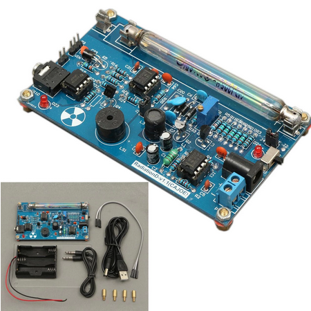
1 Counter Geiger Kit.
Incluye la placa, un porta pilas, el tubo miller, sus cables de conexion, usb, audio, https://es.aliexpress.com/item/4000229395987.html
1 ARDUINO UNO + cable USB.
https://articulo.mercadolibre.com.ar/MLA-831828838

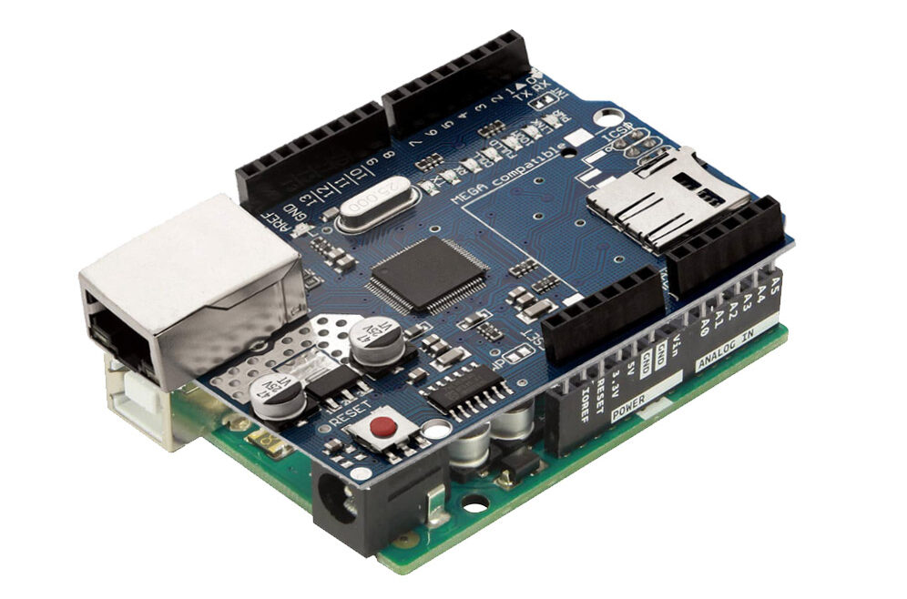
1 Arduino Ethernet Shield W5100
https://articulo.mercadolibre.com.ar/MLA-620321340

1 Cable de red para conectar el arduino al router de internet.
INSTRUCCIONES
1. Montar el Arduino Ethernet Shield W5100 sobre el ARDUINO UNO.
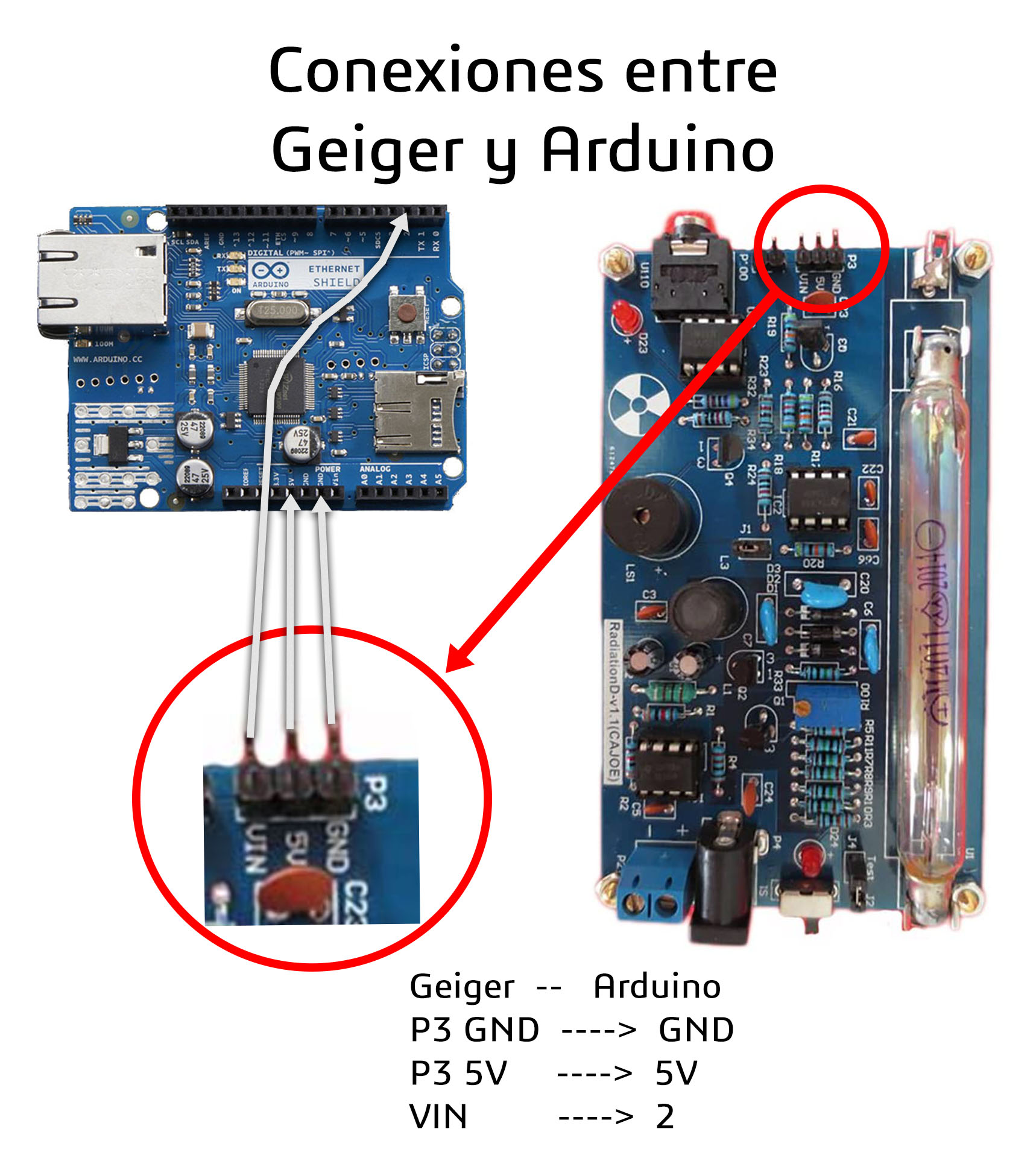
2. Conectar el cable de puente desde Geiger a Arduino
Geiger –> Arduino
pin 3 GND —> GND
pin 5V —> pin 5V
pin VIN —> pin 2
3. Conectar el cable USB desde la computadora al ARDUINO para dar energia y poder programarlo.
4. Registrarse en www.radmon.org luego editar tu perfil tomar nota del usuario y password para subir datos.
5. Software IDE Arduino se descarga desde https://www.arduino.cc/en/software luego de instalar, vamos a > Tools > Manage Library > Buscar por nombre e instalar librerias SPI y Ethernet.
6. Copiar y pegar el siguiente Codigo fuente libre https://github.com/rjelbert en un proyecto nuevo de Arduino. Luego editar la linea 142 cambiar YOUR_USERNAME y YOUR_PASSWORD por los creados en la registración de tu perfil de radmon.org
client.print("GET /radmon.php?function=submit&user=YOUR_USERNAME&password=YOUR_PASSWORD&value=");
7. Clic en el boton “SUBIR” en Arduino IDE.
8. Si no apareció ningún error…Listo ya funciona!
9. Verificar en la web radmon.org si está transmitiendo datos el sensor.
